Wednesday, October 19, 2011

A little job on the side

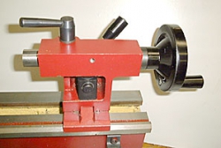
Tonight I started on a new tool holder for my lathe. I saw it on a forum to make it easier to cut threads.It allows the tool to swing up when reversing so you don't have to withdraw the tool between passes. It is made from a piece of scrap steel I found at work that was about the right size and shape.

The part I did tonight was to cut the dovetail. It is a 60 degree dovetail to fit my quick change tool post. This was the first time I have cut steel on my mill so it was a learning experience. Main part was getting the speed right for the material. It seemed to work better with a faster cutting speed than I expected. I thought I was going to cut a groove to depth and then work to the side to width. Wrong answer. I needed to cut down on both parts I milled out before switching to the dovetail cutter.


The next part will be to cut the step on the side to support the cutter holder and then it will just be drilling for the depth adjuster and a key to stabilize it.

Here it is sitting on the toolpost. I am really pleased that it came out as well as it did.

Part of why I am taking so long on my build for my router is to learn machining as I go. This won't be part of the router but it will make it a lot easier to cut threads to make some of my own parts for the motion components.

Here is a video from Bogstandard on madmodder.net (<- a link to the forum discussion) that is the design that I am basing mine on. Don't expect me to make one as nice as his.

Tuesday, October 18, 2011

Well, Actual progress

I finally have gotten materials and tools to the point where I can start doing some building. This is the lead screw for my Z-Axis. It is 1/2-20 Acme rod. I turned one end down to 8mm and threaded it to hold two bearings and a nut to hold them on. I also made the anti-backlash nut for it. It is made out of Delrin and is 3/4 in externally with a lip that will be clamped down to take up the backlash. It is going to be much like the system that they use for Sherline mills. I was tuning one up at work and liked the simplicity of the system. The leadscrew is about 18 in overall. I want to make a wide stance to help keep it steady.

The other end is turned down to 8mm to hold one bearing and the remainder is cut down to 1/4 in for the flexible coupling for the stepper.

In other news, I have all the electronics working. I have 1 nm stepper motors for each axis and two ways I can run it. Either with a parallel port controller or I also have my grblShield with the g-code interpreter already loaded. My next phase will be to make the Z-Axis unit and linear bearings.

See, and you thought I had given up.

Thursday, September 29, 2011

Long time without posting.

Well, sorry for not keeping things up to date. New semester at work and not much progress to talk about doesn't make for that interesting of posts. I will see about posting pictures later but for now, I will have to just tell you what I have done lately.

The most interesting thing I have done towards my CNC router is fabricating the lead screw for the z-axis. I picked up some 1/2-10 Acme rod for the screw. I made two of them for practice. Then, I turned down and threaded one end for for bearings and the other for the motor coupling. After spending a lot of time looking at anti-backlash solutions, I decided to make my own. They are actually pretty low tech and easy to make. I should be receiving my tap in a few days  I figured I would go ahead and buy one since I will be experimenting and I would need enough of them to justify the purchase. I have some UHMW-PE, Delrin, and Aluminum to work with. I have not decided which I will try first.

I have figured out the final arrangement of the drive for the x-axis and am debating for the gantry. I have chain and I have enough acme rod. I see advantages both ways. Most likely, I will go with the chain on the y-axis as well just to make it easier to calibrate having the same mechanism.

I have also been spending time working with manual machines to figure more out on how I want to have things work.  Whenever I have some spare time and materials, I have been making more tooling for my machines. Most recently, I got some stock roughed out for some more tool holders for quick change tool post on my lathe and starting to design a dividing head for my mill. Hopefully the weather will change soon so I can spend more time in the garage working on things. When it is over 100F, I really don't feel like spending too much time out there.

Wednesday, August 24, 2011

Still plugging along.

Nothing really to show or talk about that much. I have been playing with a Fez Panda II to see if I would like to use for a controller. It is an interesting board. Not the same as an Arduino but some similarities. It has a 32 bit Arm processor running at 72 MHz (I think that is the speed) and more ram. It is actually cheaper than the Arduino Mega and has about the same IO capability. It also has a built in SD card reader. The downside is that it is more electronically delicate than the Arduino for one thing. I burned out the voltage regulator on my first one when I accidentally shorted out a servo control line (I wasn't wearing my glasses and stuck it in the wrong row on my breadboard) *poof*.  I will try to replace the voltage regulator to see if I can salvage the board but I doubt it. It is also pickier about it's supply voltage than the Arduino. It also is a bit more complicated by matching the firmware to the version of the libraries. The biggest problem I have seen is that there is not real high quality documentation and really crappy example code.

I have been having mixed emotions programming it in C#. There is a bit of a learning curve but the language is ok. I don't like not having the delayMicroseconds() that the Arduino has.It is not a major problem, I just did an empty loop and adjusted the count to get smooth motion from the steppers. Just annoying.  For this setup, I am using some little Pololu stepper controllers. They seem to be more reliable than the Easy Drivers I was using before. They would work for a while and then crap out. I think it might have been heat related. Out of the 5 I have bought, I only have one that is still alive. If I get it working well, I can plug the grblShield into it just fine.

As far as the final setup for my CNC when I get stuff put together, I am not sure what I will really use to control. I will probably just switch back and forth and see what works best in practice. Theory only works so far.

I will probably stay somewhat sporadic with my updates here as I am getting stuff ready for the new semester at work and still doing a big re-arrangement in my workspace in my garage. Since it has been 103F every day, I don't work for long stretches at it in the garage when I get home. Thankfully, summer is winding down and it will start cooling off.

Sunday, July 24, 2011

I keep getting side tracked.

Well, here is the update.

I picked up some new stepper drivers from Pololu to experiment on. I also wanted to test out a .NETMF based one so I picked up the Fez Panda II.

Well, the Panda was a pretty nice board. Notice the "was"?  Well, one of the joys of getting older is that my eyesight is not that great any more. While testing out a servo, I plugged into the wrong row on the breadboard and fried the poor little board. Ooops. Oh well.

My first impressions of the board were actually pretty positive. There are some things I prefer about the Ardiuno, and some about the Panda.  The panda is faster and has more memory. It also has a built in SD card slot.  The IDE has more features but I don't really put that much of a plus in its favor. C# isn't too bad and the ability to print debug statements is an advantage. If I were going to build a graphical interface for an LCD and stuff like that, it seems to be a pretty robust set of tools. That said, I wasn't impressed enough to wait and buy another one to work with. Maybe later for some other project.

I was doing some tests with the Pololu stepper drivers and so far I really like them better than EasyDriver boards I was using. The EasyDrivers were OK, but they began failing and I was down to one working board out of the 6 I had bought.  At present, I don't have enough code to think about going with something besides grbl for a real machine. It is a lot more complete but I have been taking some of the code and converting to the Arduino IDE. The main reason I am going that way is to be able to switch boards more easily. The grbl code is pretty deeply tied to the 168/238 and I would like to move over to the Mega. I was testing out my ideas for writing directly to the ports to sequence the steps and that worked as planned. Actually, better than I had thought. I was having to increase the delays to allow the motors to keep up. In the 1/16 step mode, I was down to something like 90 microsecond wait for the motor to respond.

Now, I need to start doing some work on the communication. The plan I am working on is to lighten up grbl by using a pre-processor on the host computer side to be able to do things like units conversions and configuration storage on that end rather than keeping it on the arduino. I have been working with switching the stepping mode kind of like a transmission to switch between rapid motion and real cutting.  I won't really be able to tell that much until I have some mechanical motion to see what it is really doing. Right now, I am just sending a fixed number of steps and directions. Some of the ideas I have for the motion control are not as sophisticated as grbl but I really don't think that some of the stuff that they do is totally necessary. At cutting speed, the motion will be slow enough that a simple acceleration scheme might be more economical. Of course I might be wrong, but I already have grbl installed on another board and I don't have to depend on my ideas.

The other thing that has been occupying me is I finally got my mini-mill from Harbor Freight. I had to reorganize my garage to be able to set it up and that was a lot of work. How this relates to this project is to be able to work out some of my ideas for linear motion. This week I will be able to get it all set up and actually see about cutting some metal. I will be tight on space for a few more weeks until I can get the boat out of the way in the garage.

Wednesday, July 6, 2011

Background for software control of a CNC machine

Well, a few people have contacted me or commented so I guess I will go ahead and talk about the software control.

I am pretty opinionated so some might come off sounding a bit heavy handed but I'll put on my big boy pants and step up.

The normal operating systems we use for a general purpose computer are not real time operating systems. That means you can't guarantee when things will happen. You can't really do things that require millisecond precision in timing. That's fine. Most stuff with CNC doesn't require it. The only thing that is critical is the reading of a few sensors (limit switches and emergency stop buttons) and the stepping of the motors. Everything else can happen when it happens. Software like Mach3 and other stuff tries to come close to the millisecond timing by controlling the parallel port and does a pretty good job. If you don't have a lot of other programs running and can actually find a computer with a parallel port, you are set. Like it or not, parallel ports are going extinct. They are already somewhat unusable on some computers like laptops. Pretty soon, they will be an historical footnote like the IEEE488. (We all remember those, don't we?)

Another thing to consider is the communication rate. The first thing I keep hearing whenever someone says something about CNC control over USB is you can't communicate fast enough to control it properly. Somehow, the fact that we commonly have printers and plotters that have just as demanding positioning and control do just fine over a slow serial connection escapes them. Sitting on my desk next to me at work, I have an old Roland CAMM3 mill/engraving machine. It works with serial or parallel ports just fine. In fact, the only thing wrong with it is that it has a really small work envelope and it has a funky old control interpreter that isn't supported by more modern software.

With a little Arduino or the like, it doesn't run that fast compared to modern computers. My little Arduino runs at 16 MHz. For control of a few stepper motors, it is plenty fast though. The basic communication I intend to put together will do four main things:


  • Control the stepper motors with an even smaller subset of commands resembling g-code
  • Watch for fault conditions (Limit switches and  emergency stop)
  • Set control pins
  • Report status.

Everything else can be done on the host system. Now, I am not claiming to be an expert on stepper control. I can send commands and make one move back and forth but the real intricacies are a bit tougher than that. The good thing is that Siemen Svale Skogsrud wrote grbl which has all that goodness already figured out. I have never communicated with him, I have only been reading his code. It is very pretty code. As with all open source software, he has written his code to scratch his own personal itch. It just doesn't do what I would like.

Well, that's enough for the background. More specific stuff later.

Monday, July 4, 2011

Still alive.

Well, there has not been much to talk about. The progress is pretty slow. Some has not been as quick to implement as I had hoped, some looks promising. I have also been spending a lot of time waiting for stuff to ship to me. I picked up a bulk package of bearings, some glue, a drill bit. That kind of stuff. I have also been waiting on my little milling machine that has been on backorder from Harbor Freight for a couple months.

I have been doing a bit of hardware stuff and a bit of software.

Hardware first.

I have been probably over thinking the linear bearings but there have been some things that bothered me. I prefer to make the rails out of aluminum but I don't like running hardened steel bearing races on aluminum. My current solution is to make some wheels for the bearings. I have a few small sheets of UHMW polyethelene and used that. I cut out a bunch of little squares of the UHMW and drilled out holes for the bearings with a 22mm Forstner bit. Then I took them to the lathe and cut them down to final diameter. It sounds a lot easier than it was. I had to figure out how to cut them out concentrically. The final solution was to make a plug mandrel that I could press fit the pieces on and then a small face plate on the lathe to press them against.  I pinched them between the face plate and the mandrel with the tailstock and let them spin a bit on the live center while tightening. As they tightened, they centered themselves. I made enough for the entire router and a handful of extras.  They are a snap fit on the bearings and seem to stay on well enough. I did get some 3M 90 adhesive that was supposed to stick to the polyethelene but it was pretty much a waste. It was messy and after a day of drying, it was still possible to pop off the wheels. It didn't stick to the steel well enough to bother with. I might as well just run a bead of epoxy, CA, or just paint on each side of the wheel to make a wall to keep the wheel from sliding off.  If the UHMW wheel doesn't stay on the bearing, I can make some replacements with something else that glues better. The carriages will be much like the ones from cncrouterparts.com:

Linear Bearing Carriages from cncrouterparts.com

The difference will be that I am going to make mine in wood and in two parts. I have a set of theirs and they are really nice if you are going with steel rails. They would eat up an aluminum rail really quickly.


On the software side:

I already have the g-code interpreter on the Arduino and have had it running the motors for quite a while with the grblShield. I really like the board. The software, not so much. Actually, it is some of the most well written code I have ever seen. I just don't like how it is designed. Basically, you just dump g-code at it and it works.

Here are my main gripes about it:


  • At present, it doesn't run on anything but a plain Arduino with a ATMega328 which doesn't leave a lot of room to do what I want. Little memory and few free pins. I would prefer to run it on an Arduino Mega with a lot more input and output capability and more memory.
  • All the code resides on the Arduino. There is no reason to put all of that stuff there. It doesn't need to do all the settings. It doesn't need to do all the unit conversions. All I need to do on the Arduino is to run the steppers and set and retrieve info from the pins.
  • There is no flow control to do things like zeroing, emergency stop, or spindle control. The have some preliminary stuff there to implement limit switches but that is about it.
  • It implements a subset of g-code. No variables, subroutines and such. 
  • There is no flow control to handle things like bit changes, jogging, or pausing.
  • It uses an older tool chain for development which I just don't like. 


I looked at the alternatives. The closest one was Firmata. It works similar to the MIDI protocol but when I started working with it, I found it really lacking. All the client libraries I found do not implement the protocol well enough to use it. Specifically, they are missing the sysex messages and the string passing. By the time I would implement that, it would be a lot more work than just creating my own protocol. It is just serial communication, it is not that hard.

All I need on the controller board is absolute positioning with a subset of g-code, reading and setting outputs on the other pins, and to be able to set an emergency state to stop the machine when things go really wrong. On the controlling computer, all the unit conversion, settings and calibrations, g-code interpretation, zeroing, spindle control, limit switches, jogging, and such can be handled. It also allows the possibility to switch either component. I could go with a faster controller with more memory like the Netduino. I could also write a more sophisticated host software to run everything.

Now, here is the question for readers here:

Do you want for me to get into the coding part as well here on this blog or do you want me to just focus on the hardware and machine design?

Thursday, June 2, 2011

Side tracked by my spindle.

Nothing to really show right now. I have been working on my spindle. I picked up an ER11 collet holder and set of collets that took a while to get here from Hong Kong. The holder I bought has an 8mm shaft. The plan is to use 608 bearings (skate bearings) for the spindle. As shipped, it would have been a press fit for the bearings but I want to be able to replace them easily. So, I chucked it up in the lathe and spend some quality time with some emery paper to bring the shaft down for a slip fit for the bearings. Well, it took quite a while with that hardened shaft.

While I was doing that, I also finished adjusting my cam lock for my tailstock on my lathe.
Tailstock cam lock kit from LMS
I really like it but it was a pain to get set up. The installation was dead simple. Drill one hole in the web on the side of the tailstock and put it together. The pain was figuring out the orientation for the interior nut so that the threads line up where the quarter turn will pull the bolt tight. If you turn it one way, the thread is 1/2 turn off so it won't tighten quite enough to lock. Being a slow learner at times, the real solution was to use my center punch to mark one side of the nut so I could see when it was rotated 180 degrees. It would have been much simpler if I had done that from the beginning.

I did make a test run for the motor for the spindle. I have a 350 watt brushless motor:
Motor from Hobby King
  and a brushless motor contoller:
Brushless ESC from Hobby King
I started up the motor and ramped up the speed part way using an arduino. I am going to look later at controlling the spindle with my grblshield stepper shield but I have been waiting for the developer of grbl (a g-code interpreter for arduino) to get back to development so I can ask him a few questions regarding the spindle and limit switch controls. For now I am just running it with a different arduino.

The general idea for the spindle is like this:

But I am not really sure on the component placement yet. I think it will be shrouded with a place to hold the speed controller and also maybe a fan for cooling. I don't know how hot the motor will run under load and at speed.

Thursday, May 5, 2011

Things are moving along

Well, I have not been posting lately but I have been doing things.  I have my arduino based controller working and responding to g-code.  Just to fill you in, I have a grblshield and and arduino. The grblshield is a 3 axis stepper controller board for the arduino. So far, it is really nice to see motors actually moving.

I have decided that I will play with the smaller cnc machine for now. I will be using lead screws on this one. I have everything I really need for it.

I had considered using my little Proxxon X-Y table but I think I will reserve that for my little drill press.

Tuesday, April 26, 2011

Unhappy with bearings.

I have been playing with the bearing idea that I had. I am not really happy with them. I could make some adjusters for the bearings but I don't want them that complicated. I am going to have to give this some more thought. When I have a better plan, I will post.

Thursday, April 21, 2011

Test fitting the bearings and guide tube

My general overall impression is that this is going to be a good solution. By no means is this sample good enough to use but I was a bit anxious to see how things fit together. I just drilled the holes freehand because I really didn't know how things would fit together. There is a lot of stuff to potentially interfere. There are several clearance factors:
  • Clearing the fillet on the inside of the angle
  • The nut's clearance on the inside of the angle
  • The interference of the nuts and screw heads
 I was also concerned that the lengths of the screws were right. I had tested with some smaller screws for rough measurements but I knew that many things can go wrong once I started shimming things. The 25mm screws give me enough room for two shims and I could probably handle 4 flat washers and some lock washers on the 40mm screws. Right now, I didn't put any shims so it doesn't line up that well with the centerline of the tube but no point in messing with it until I have the spacing right. There is still lots of room for adjusting things.  I will be mounting the center bearing closer to the edge so I really won't need that many spacers on the short screws. I will probably need to counter-bore the the angle to seat the screw heads squarely. No big problem. It would be simpler to use the architectural angle that has a square inside corner but I will work with what I already have. 


I will now measure how far I need to space them to leave room for wrenches and make a fixture to hold the pieces for drilling on the drill press. It is also going to give a lot of space to mount other stuff to the complete carriages. I was also concerned that it would not be rigid enough but once I tighten up the screws, it stiffens up nicely. I could even make it more rigid by adding another bearing and screw in the middle but it would complicate getting things aligned. I could alternatively go with just some spacers.

Wednesday, April 13, 2011

Metric Rant

With the current world connection created by the Internet, I frequently hear people complain about the US measurement system. Let me let you in on the real problem with metric adoption: We really can't get metric stuff.

I ordered some screws for mounting my bearings. Regular skate bearings (608) have an 8mm bore. I can't just go up to the store and say, "I'm looking for some M8 screws. Let me have a box of 25mm and a box of 40mm." If they have any at all, they will be maybe one length and in little plastic bags of 4 screws for $3 or $4 as opposed to $0.06 for a SAE equivalent.

Instead, my only option is to order them online. Ok, first, I have to find a vendor that will sell less than 50 lb. boxes. Once I find some, I have to go ahead and order many more than I need or end up paying the same amount of money for less screws. I ordered a bag of 100 of the 25mm and another bag of 100 40mm. Well, I also needed washers and nuts. On top of that, I pay almost an additional 20% for shipping.

I had someone that was really surprised when I was talking about building my CNC mostly out of wood and gluing things together rather than all bolted together being a money saver. My fastener purchase was the single most expensive component of my CNC build. This includes things that I have had shipped half way around the world from Hong Kong to the US. The fasteners cost more than any other single component.

As long as we cannot just go down to a local store and things that are really metric, we will not convert to metric. We have this fake metric adoption where you get things in some funky measure like my coke can sitting next to me has a metric measure: 355ml.  It is the same 12 ounce size as it was before, they just put a conversion on it and say "*Poof*, it's metric." Same as when I work on my bike. Some things are really metric, some things are fake metric. We have things that are 25.4mm and 31.8mm which are the same size as when we were using non-metric measure 1", 1-1/4", 1-1/2" and such. So, not only do we have that, we also have them with other dimensions where the measurements that really are metric. So, we have a 1" bore on a 80mm shank so much that we just about have to carry around multiple measuring devices at all times. We also have to keep around two sets of tools because some parts are metric, some are not. I have duplicate wrenches, allen keys, measuring tapes, etc. One set in metric and one SAE. Even more fun is when the parts you are working on have a mix.

I can work with both systems and it doesn't really make any differences as they are all arbitrary. They both have advantages and disadvantages. I just wish we would have one or the other. Playing mix and match with both is just an absolute pain in the rear.

Sunday, April 10, 2011

Finalized Linear Bearing Plan


Ok, I have been thinking, and overthinking, the linear bearings. I have been unhappy with the ones that I have tested out before and finally have figured out what I want to do. I have not been happy with the idea of running hardened steel bearings on aluminum. I didn't want to mess with steel angle tracks because it is not as easy to work. I also wanted to keep the cost down. Here is the cheapest and easiest to work with plan that I have been able to develop.


This design uses 3/4" steel electrical conduit (EMT) for the rails.. It is straight and not expensive. It will also wear much better than the aluminum. A 10 foot piece was $4.33.  The 5 foot pieces I bought today are under $3 a piece at the borg. I could have gotten cheaper but I didn't want to mess with putting full 10 foot pieces in my car or driving around shopping.  If I were going with a more powerful router, I might consider using a thicker wall pipe or larger diameter tubing but I can't see it for a small router.

The bearings will be mounted on 3/4 in aluminum angle. This could be modified with larger angle to accommodate larger diameter tubing but I already have plenty of 3/4 in.  I ordered the screws today also. For the ones between the angles, I figure that 40mm will be plenty long and 25mm for the ones that stick out on top and bottom. I went with M8 screws. They are the right size for the 608 skate bearings without slop and will be stronger than smaller screws.  I also ordered lots of washers so I can shim the bearings to ride centered on the rails. I might put more bearings on each carriage mainly to make it more solid in case the angle starts flexing. I will see how it works once it is put together. I am also going to think about adding a shield around the bearings to keep it clean. Maybe some wipers on the ends.

The rails here are drawn to scale. The 3/4 in conduit is 0.931 in. OD. I plan on attaching it to the conduit with screws every 3 or 4 inches to tie the rails and support together. I might notch the support rail for the conduit to rest in but I will probably just add an epoxy fillet to secure and support the rail.  This rail assembly will have a wider backing plate behind it for adjustment.

If you would like the model for SketchUp, here is a link.

Wednesday, March 30, 2011

Manual machining stuff and rethinking bearing rails.

I have been doing a little manual machining to get ready to make some stuff for my CNC ideas.  I finally figured out how I can use my milling attachment on my little 7X10 lathe.

To make the milling attachment work, I added a milling table which is from an old Incra jig right angle fixture.


To mount it to the milling attachment, I just added a solid block of 1-1/4" x 1-1/4" aluminum to both clamp it into the attachment and also to provide a backing for the extrusion.


Next,  I will also make a vise and then a tooling plate for attaching other things like my rotary table.

In other news, I got a large bag of 8mm hex head cap screws for mounting 608 bearings. Of course I forgot to order some washers but that is life. I will pick a few up at the hardware store while I wait for an order of them to come from online.

I keep rethinking my bearing rail ideas and am considering going to a steel tubing rather than the aluminum angle for the bearings to run on. I just hate the idea of running the hardened steel bearings on something as soft as aluminum. It would be easy to make but I don't want to have to keep adjusting and replacing rails. I could go with a steel angle but it leaves me with the same problems and none of the advantages of using the aluminum rails.

I also got a shipping notification for my grblShield for my Arduino. If you are not familiar with it, it is a 3 axis controller board that attaches to an Arduino microcontroller. I have a parallel port breakout and stepper controller but I really want to try running it from the Arduino instead of the host computer. It is a trade off but I think it really is a better way to go. I can use my parallel breakout on a CNC lathe I have at work to play with and have all the electronics for another system using the arduino and 4 easy stepper drivers.  My ultimate goal is to get to the point of being able to do 4 and 5 axis routing but I am going to build the first machine to use to make further experiments.

Friday, March 11, 2011

Still alive.

Things have been hectic in the real world day job and have not had time to add any real information. Here are the things that I have been thinking about for my machine in the meantime.


Structure:

Ok, I have the metal for my rails, but I am not cutting wood yet until I have a firm plan with all the details. I also need to make a sub-fence for my router table to fit around the bit that I will be using to cut the support rail profiles. Shouldn't take that long but I have not been that panicked to just build without thinking things through. If any of the readers here are that anxious to just "get something made", I really suggest going with one of the proven designs. This one may actually suck. I am fully prepared to accept that outcome. If I was just wanting to get something made myself, I would have just gotten one too. I am designing this to test out my own ideas.

At present, the two design components I am deciding on are the Z-Axis and routing and idlers for my chain. I have a few ideas for the idlers but I need to sit down and test some parts to see how well it works. The main part is to hold the outer race of a 608 bearing. Maybe a press fit, maybe a plate to hold it into a recess. I have to clear off my drill press area to make some test pieces and see what I like best. The Z-Axis will have to fit around the idler so it will have to be the decision on the idler first. I also have to figure out the routing for the chain for the X-Axis as well. I am most concerned about getting it out of the way from swarf or sawdust. I might just have to make the box for the base taller to give me some room.


Controller:

I ordered a different motor driver board for my machine. I have been really thinking about the idea of making mine Arduino controlled. Yes, everyone uses CAM software to move the machine around.with parallel port control with Mach or EMC2. Well, you know what? How do you explain the fact that there are people running CNC stuff quite effectively with USB connection to an embedded controller. RepRap, Makerbot,  and a newer one named Dank that I found through an article on Make Magazine. There are others as well. Planet-CNC has a really nice little USB based PIC controller that  handles the motion control. Also, there is a whole market built up from doing motion control over USB. Just about all printers and many engraving machines use USB control. No, they don't do really sophisticated G-Code with subroutines and such. That's fine. I am not looking at doing a lot of high end G-Code. I am going to use other design software that generates it like Inkscape and SketchUp and run computer generated code.

Enough for tonight. More soon.

Tuesday, March 1, 2011

Just a heads up on another project.


Mike Calvino has a project over on Kickstarter.com that is a really good example of a well though out gantry design. I see so many bad examples, I want to make sure and point out a good one. Most of the ones I see on this kind of project look like a 15 ton gantry crane. In comparison, this one looks positively elegant.

I wish I had the room for something like this 5 Axis monster.

Friday, February 25, 2011

Refinement of the gantry plan

There, I am much happier with this. I offset the bearings to get them under the router.This does two things. One is that it puts the center of gravity more balanced over the bearings. The other is that it makes the bed much shorter.  This model is just under 5 feet (57 inches) which takes a foot off the previous draft. In effect, it is the cutting length of 48 inches plus the width of the bearings plus a little extra to give some room to mount limit switches. I gave it 1/2 an inch in this draft but that is a pretty tight fit. I will go ahead and make a full 5' for the final version which is the length of the angle I ordered and also the length of the baltic birch I will use to make the rails for the bearings.  This will give a bit more room for the limit switches and clamping for the workpiece to the table. Also, the beam of the gantry is a separate piece. I will bolt the three sections of the gantry together so it can be disassembled. This will allow for adjustment to square the gantry to the cutting surface and to shim it to make it level as well. 


 With the X-Axis all the way to the right, the cutting axis is past the 2' x 4' sheet   With the X-Axis all the way to the left, the bearings are still supported by the rails. I could go with a more square shape instead of the curve but the curve will be nicer. It is not too hard to make that kind of curve. I will be making a lot of the gantry out of 1/8" plywood (4mm or so in reality). They sell it as door skin and I have a couple sheets of it left over from my last boat building project. It is luan plywood. This thin stuff doesn't have many defects and bends quite nicely.

In keeping with my goal of making the gantry light, I will be making the internal blocking out of ply and red cedar. It is easy to work with, cuts well and is nice and light. I might go with a light glass over the wood in places just to tie it together a bit better and make it less susceptible to humidity. Depends on how I feel when I start putting it all together. I still have to think a bit more about how to fit in the drive mechanism.


One other thing I have to do is to make a chip guard for the bearings. I need to maybe move the bearings down a bit and cover the rails to keep dust off of them. This might mean making the rails a bit smaller. Not a big problem. As they are right now, they are very much over designed for the load that they will carry. Since they will be fully attached along the length of the bed, they will be quite strong.

Thursday, February 24, 2011

Rough Sketches

 Still thinking.  I do have some of the ideas getting firmer. The overall size will be big enough for a 2' x 4' panel. To get the full cutting area, I will have to make it longer than the 4' so the offset of the router to the gantry will be within the cutting envelope.

I plan on all the bearing surfaces and the bearing carriers to be interchangeable.  I will have to mock up some pieces once my metal order comes in. Right now, the rails for the bearings are right at 3" ( 85 mm)  I can go a bit smaller to give me more room. The bearings themselves, I am deciding to either put them on a bolt with either a hanger bolt or glue a stud to mount them on. The number of them can be variable. At present I am putting just two on each end but it could easily have more pairs to distribute the load.

The table itself will be pretty deep. It is going to be a torsion box and the interior space can have two parts. One thing that comes to mind is to make a vacuum table for keeping things positioned. I probably won't because I don't have a vacuum pump or dust collection system anyway. Also, part will be partitioned off to house the electronics.  Might as well keep it out of the way. Right now, I am around 8 inches deep for the base. That could be pretty nice for keeping things out of the way. I could even make it a storage box for parts or even house the computer in it.
The Z-Axis is a bit problematic. I will have to think about it some more. The model I have been working with doesn't look too bad but it does make for a lot of dead space on the end of the table. It doesn't really hurt anything to have that extra space. It can be used but just not for cutting. Maybe a monitor mount and keyboard tray?

I drew up another version that had rails on both sides but it looks like it doesn't really gain me anything.  More thinking to do. If anyone has a better idea, speak up. I am open to suggestions.

Wednesday, February 23, 2011

Bearing Decision

I have been debating how I want to deal with the bearing surfaces.  I was going to go with a thinner angle stock to line the bearing surfaces and glue them on and anchor them with screws at the ends. After lots of consideration, and a quick consult with someone much more experienced with glues and supporting other people building from plans, I have changed my mind. Thanks MIK for talking me out of it.

The thinner would be sufficient to handle the load but there are other considerations.  I am planning on this CNC being able to be built by others. Gluing aluminum is not a real easy task. It takes a lot of prep work and other people might not be as able to have the resources to do it properly. If not glued well, it will have a tendency to pop loose and it being on disparate materials with different coefficients of expansion, it will be prone to trouble if you are not careful. I am going to go ahead with 1/8 " (about 3mm) 6063 aluminum angle and attach with countersunk screws. If I go thinner with the angle, it will tend to deform around the screws. It's not that much more expensive and it is still pretty light. I can live with it. Online Metals should have it to me in a few days.

The .other things that I have been waiting on have finally arrived. I decided to go ahead and get a really nice fence for my router table. It will make preparing the stock much easier and besides, I wanted it. I picked up the 17" Incra LS. Gold and red anodized aluminum is so pretty. It is a bit extravagant but a real pleasure to use. To prepare the stock for the angle, I also picked up a new bit for my router. I bought this one from Grizzly for $20. It's a lot easier than messing around with cutting the angles on the rails for mounting the aluminum any other way


I have also made one more decision. I am going with a 2' x 4' cutting area table for this first CNC router. I don't yet have things organized to a point where I can fit a full 4' x 8' unit right now and if I went much smaller, I would be disappointed by the size limitation of anything smaller. 2' x 4' sheets are easy to come by at the lumber yards and easy to fit in the car.  It will also be big enough to make 4' wide parts for a larger machine. I can live with that.

Sunday, February 13, 2011

Slowly getting back into the workshop.

Well, no progress on the CNC but It was finally warm enough to go out and get some stuff done. I finally installed the cam lock for my lathe tail stock. I have had the box sitting here for a month but it was just too cold out in the garage. People that live up in the land of ice and snow will laugh at the temperature but when you live in what is basically the tropics, a freezing temperature just makes it miserable when you are accustomed to lows in range of 75F.
Not mine. Get yours here
It was a pain to get it turned the right way so it would lock on the ways. The alignment is different with the lock rings on so it was a matter of take it off, test, take it off, test. I finally got smart and punched a mark on the body so I could tell one side from the other. I still may need to shim it a bit with another washer. This was one of the most aggravating things about  my lathe. Having to stop and get in with a wrench to adjust the tail stock was a pain. There was really not much room so it meant turning 1/6 a revolution at a time to turn the nut.

I will go out in a bit to work on putting the other things on. I also picked up a lock for the saddle and a stop for they way. Those are quick and easy and just bolt into holes that are already tapped.  The main reason for all this is that I have also got a milling attachment for the lathe and I need to be able to lock down the saddle while milling.

This is really not related to the CNC project because I am forcing myself to use all off the shelf hardware for my CNC router. The whole process is like the chicken and the egg. It would be really easy to build myself a CNC machine using the machine shop I have access to at work. I could also just order one of the kits and bolt it together. The parts are readily available. CNC-Router Parts  and Fine Line Automation have some nice components that I could just buy and bolt together. I have actually bought some stuff from them for another project I am playing with. That is something different. With this project, I am just working on testing out my own ideas for building something different. A big part of it is that I don't want to use things that are not commonly available. The only things that I am using that are not regular hardware store fare are the electronics and the #25 chain. The same thing could be done with bicycle chain but I got such a cheap price on the chain that I cannot pass it up. I picked it up from Surplus Center. 60 cents a foot was quite an incentive.

There are some projects that are cool but totally unreasonable for people to reproduce. I look at projects that go like: Well, just take the leftover parts that are from 4 or 5 old CNC machines and then say, "Wow, I made a CNC machine!"

One the other end of the spectrum, you have projects like the Global Village Construction Set. The components they make are cool but completely unrealistic. Yes, if you have a fully equipped machine shop and welding equipment, you can make just about anything. What a surprise.

The OpenSourceMachine is a much more reasonable project. It is geared to making a machine shop from scrap that is really available. They are making a lathe, milling machine, and several other machines using things like engine blocks. This kind of bootstrap operation will do much more to help people make things starting from scratch.

Thursday, February 10, 2011

Brrrr. It's cold.

No, this is not an abandoned project. It is just too cold to work out in the garage and other stuff taking time.  Along with this project, I also have some work to do on my lathe and "those people" at work seem to want me to actually do some work.

More posts when there is something to say. Thanks for dropping by.

Sunday, February 6, 2011

Will it cut steel?

I see people keep asking if a CNC router would cut steel and aluminum. Why would you even want to?  It would be much simpler and cheaper to retrofit a metal cutting machine for CNC than trying to push a CNC router that hard. Even buying new, you could build a small CNC metal cutting mill for under $1200. A cheap SIEG X2 from Grizzly costs $500. You can pick up some steppers and a controller and you are in business. The only thing you would really need to make are the motor mounts and people sell those already made if you don't have the facilities. If you have the space and some patience, you can pick up a large mill off the used market for not really that much more money. Later, I might even make a CNC metal cutting mill. It would be fun to work with but it is not the same thing.

Tuesday, February 1, 2011

My Linear Bearing Plan

I have been thinking about this a long time. I don't like a lot of the linear bearing systems that are available. The nicest ones, are too expensive and generally too heavy for what I want for this machine. At the other end of the spectrum, the cheap and simple V-bearings, I really don't think are robust enough for long term use. I think that they make too small of a contact point, and will start eating up the rails with nicks over time. I wanted to design something that you could just go down to your local big box store and without many specialized woodworking or metalworking tools or skills, put together in an afternoon. I also wanted to leave the option for adjustment to keep them aligned and to be able to add bearing surface to make them stronger.   There have been bearings mounted on angle for a long time. It is simple and effective. It is just hard to mount them to anything to make a full bearing because they are odd shaped. My way around this problem is to use a readily available molding profile that they sell at lumber yards. They sell little filler strips that are triangular with 3/4 in sides. This is perfect for filling in the angle and giving a mounting surface.

You might need to knock off the apex of the angle to fit into the angle but this is quick and easy with a plane or sanding block.  This comes out a bit over 1 in wide at the base which can be sanded off, filled in or just ignored, depending on your aesthetics. You can then edge glue this to a rail that can be as wide as you would like to spread the load. If you would like, you can add additional bearings on the moving units to make a stronger support for higher loads. The stationary angle will only a bearing surface. You would not need to get very thick angle. It is being supported by the underlying wood and not structural. It could be glued on or anchored with screws either at the apex of the angle or along the edge. Just somewhere the bearings do not run. If you want a more long lasting surface or something stronger for working with harder materials, go with cold rolled steel.  You get the idea.

The movable bearing sections can be built up into units that you can mount the gantry or the Z axis depending on the location. The example here is a bit thin on the support but that is up to your final design choice. To make longer rails, all you need to do is butt the rail sections together, fill with expoxy (J-B Weld or such) and sand it even.  The rail can be almost fully supported except for the edge to give clearance for the bearings.

The last part would be how to support the overhanging bearing. That can be done with a small gusset that will support the extended arm or you can also make them into bolt on sub-units that can be adjustable for tracking and play. You can have multiple sliding units on each side of the gantry to broaden the stance of the gantry to make it more stable.

This is just a rough idea and the profiles will be developed more to fit in the different locations. Yes, I know there are other ways to make the profile to fit inside the angle. I am going under the assumption that people might not have a tablesaw, router table, shaper, chamfering bit for router, chamfering plane, drawknife,  or any of the other myriad ways that you could reproduce this profile. Again, people who may not have the woodworking skills or tools are the audience for this type of construction.

Monday, January 31, 2011

Why would you build a CNC?

My last major project was building a boat. It was much the same as building a CNC router. You don't build a boat to save money. You can buy one much more cheaply than building one. The only rationale for building a boat is that you want to build a boat.

As I do my planning for my CNC router, I think about my rationale is for building a CNC router. For me, it is for fun and for a platform for my real goal of working on the coding end of it. Actually, for not that much more money and a lot less effort, I could have just bought one of the Chinese pre-built machines or one of the kits. Something like Zen Toolworks or Buildyourcnc.com would be a lot less hassle. They are not really charging that much for them when you consider the extra shipping for ordering from multiple vendors and the time spent on sourcing materials, let alone the design time. If I factored my design time at my normal pay rate, I would be much further ahead just buying a pre-built machine.

If I were using a CNC router commercially, or even depended on it slightly, I would seriously lean toward one of the commercial products. At the very least, I would use standard drivers, motion components, and motors. You really can't afford to have to tinker with stuff if you are doing it as a business. Readily available replacement parts beat cheap replacement parts any time. Just having a machine sit there and not be working is a losing proposition. It makes jobs late. It loses you customers.

My initial designs for my CNC router will probably be a failure. It likely will take several versions until I get something that I am happy with. I am building contrary to what have been proven successful designs. I am purposely building an low powered machine. For a few more dollars, I could have bought more powerful steppers. I want to see how well I can move things around without brute force. The other thing that I am focusing on is building a rigid machine that is light enough to be portable and inherently stable enough to move around and not have to re-level or recalibrate. If I can get these two things pinned down, I will be happy.

Saturday, January 29, 2011

Another Gantry Design

Another quick sketch for a gantry design would be a large double beam with the router running between them.. If you went with a 3" square 1/8" thick 6063 AL tube, it would be less than  16 pounds for a 4' gantry (1.6 lbs a foot). For a little bit more you could go with 4" square tubing at 2.2 lbs a foot.  Go crazy, 6" square tube is only 3.5 lbs a foot. How on earth can you justify gantries that weigh over a hundred pounds? This is still using fairly conservative and easy to work materials. Go up to thin wall carbon steel with an engineered section and you can get a lot lighter than this.  It still leaves plenty of room for a robust z axis and nothing is cantilevered out adding all kinds of funky forces into the mix.

This is not getting into really sophisticated construction techniques. It is still stuff you can bolt together. It is just looking at the properties of the materials and not just throwing huge chunks of solid materials at the problem in hopes that it will make it rigid. Spread out the footprint of the bearings to add stability. Don't cantilever things out that create big torsional forces. Use large cross section thin tubing. The idea is to reduce weight and add strength.

Friday, January 28, 2011

Exploring One Type of Gantry

This is probably not how I will build mine at this time, but one idea I have for the gantry would be like this. Just a rough sketch, but this would probably be one of the best configurations for a gantry. The tool is balanced in the center of gravity instead of cantilevered out to one side. The rails are covered to protect them from chips and dust. The wiring could be contained inside the gantry to keep it safe. Wide stance to keep the lever action on the gantry to a minimum. I added an arch to the design to increase support as you get away from the supported ends.
From the side, you can see where the spindle would ride in this system. Yes, I realize that this looks pretty massive but the structure could be built out of pretty light sheet material. The idea is to increase the section to increase the strength instead of just making the pieces more massive. This expands the distance between the linear motion bearings to stabilize it. It makes it where you have room to build a lift for the z-axis much like the nice router lifts they use in router tables. Making it bigger doesn't increase the mass as much or interfere with the cutting area. Again, the whole idea is to increase stiffness and reduce mass. All the mechanicals could be contained within the gantry and not leave wires hanging out everywhere to catch on things.  It would also give the router a finished look instead of just bolted together scrap. If you wanted to build something stronger, you can go to sheet metal and welding. Something lighter could be made from composites.

Thursday, January 27, 2011

So, what is it good for?

My last post might have come off as a bit negative but not intentionally so I wanted to discuss it in a bit more detail. There are many things CNC routers are good for. They are not just the magic wand to set up your own miniature factory. I mentioned in the last post that CNC is not good for production work and that templates are faster and more accurate. It is effectively used to make templates, molds for injection molding, patterns for casting and the like where the production speed is not that critical as you are only making a small number of items. The real use is for one-off items where it is not cost effective to tool up for a high volume production run or to be the tool to create the tools for a production run.

Complicated geometry is one of the best uses for CNC. Once you get past the whole rectilinear world of cabinet making, there are many complicated shapes that are hard to reproduce by manual methods. Smooth curves are not that easy to do by hand without lots of hard won skills. Getting three dimensional curves cut by hand that are smooth and match is not easy. It can be relatively easy with a CNC router or at least consistently.

Intricate cuts like scroll saw fretwork, inlay, and many other intricate things are easier to consistently do by CNC. You can do them by hand but unless you happen to enjoy that type of intricate work, it can be tiring and tedious to do by hand. Also, if you are doing structural work, the smoothness of curves makes a huge difference. When the curves are irregular, they don't distribute stress well. For production of circuit boards, it does not do nearly as well as the volume production methods. It does have the advantage of not needing the nasty chemicals.

Monday, January 24, 2011

CNC's Dirty Little Secret

CNC does have a dirty little secret. It is a lousy production tool.  Everything you make with a CNC machine requires that you write a program, plan a cutting path, test that the machine will really go where you intend it to go, decide cutting parameters based on the cutting tool and material being cut and set up the cutting stock. This is not a high speed process. It is wonderful for prototyping and one off type production, but not for mass production.

It is much faster to just use a pattern cutting bit in a router and do it by hand following a template. The setup is faster, it is just as precise and a whole lot cheaper. Have a set of complex cuts?  Make a set of templates.  If you want to ramp up production to mass produce some pieces, just grab a few routers and some pairs of willing hands and you can multiply productivity to pretty much unlimited production rates.

Many times, it is faster and easier to do things manually. If you want to cut out a simple shape, just measure and mark, clamp down a cutting guide, and have the piece done much more quickly than even booting the computer. You really don't need a program to cut a piece of plywood into a 1' square.

I feel better. There are many techniques available that will beat CNC routing in a production setting. Stamping, casting, injection molding, pattern routing... The list goes on.  It is from this standpoint that I can say that  I really don't care how fast my CNC machine will cut. It doesn't make any difference. Why would I care if I can get "1500 in/min Rapids" or some such nonsense. I am not routing a path from Seattle to Miami. For a one off piece, it doesn't really matter whether it takes 5 minutes or even 2 hours longer to cut something out. If I am using an expensive CNC machine to do what a $2 piece of plywood template could do faster and easier, throwing more money at the CNC machine to make it faster doesn't make it less silly.

Wednesday, January 19, 2011

Keeping the Pieces Together

What is all the fascination of bolting together CNC machines? It's as if the entire world were afraid of a little glue. Modern adhesives are stronger than the wood that they are joining. Even metal is glued together in modern airplane construction. Come on people, join the 20th Century.  Epoxy and Titebond III are great to glue together wood even if they get wet. Look up what it takes to be rated as Type 1 water resistant. We are talking boiling for 4 hours, baking for 20 hours at 140F, boiling again for 4 hours, and then testing while still wet. Regular PVA glue is great if you want to keep it inside and dry. These glues even hold pieces of MDF together pretty well, if you are still hung up on using that nasty stuff. If you have no metal fasteners, they can't eat your expensive cutters when you accidentally hit them.  Glue doesn't cause galvanic corrosion. Vibration won't loosen glue like it will bolts. Most importantly, glued structures will distribute  stresses instead of focusing them like bolts do. The proper term for the focused stress is a stress riser. Bad stuff. It makes things warp and fail.

Now, don't start thinking that I am totally against metal fasteners. They have their place. Go ahead and screw a motor down with them. Drill oversized holes and lock them together with bolts to make things adjustable. Bolt on a proximity switch. Have a screw clamp to hold the spindle down. Use a bolt for an axle for a bearing. Just don't forget that glues have their place too.

Which adhesives are best suited? Epoxy and  PVA will come into play the most. I used to like the moisture curing Polyurethane glues (like Gorilla Glue) but that was before I met epoxy. The main difference between these two glues in use is gap filling and open time. If I have a nice clean joint and it is not going to take a long time to put together, I go with PVA. If things don't fit perfectly or I need a lot of time to get things aligned, I go with epoxy. Also, if you are forced into gluing endgrain, epoxy can really be your friend. If you need a little extra support, grab some fiberglass, carbon fiber, or Kevlar. If you need to span bigger gaps, grab some fillers. It is great stuff. Of course someone will point their finger and say epoxy is expensive. Not by a long shot. You want expensive? Go compare epoxy with polyurethane glues on an ounce by ounce basis. Polyurethane glues are much more expensive. Also, they don't fill gaps nearly as well unless you count non-structural bubbles of foam. One thing to note: Epoxy will not be as strong if you clamp it hard and squeeze out too much of the glue. PVA works better with plenty of clamping force. Read the instructions on the bottles even if you are used to using them. I found out some mistakes I used to make with some glues. One example is polyurethane glue. I didn't know for a long time that you should pre-moisten the surfaces with water.

What about comparing the price of glue to the price of bolts? Well, you can look at some of the fastener kits that come with some CNC kits. One kit I know of comes in at $120. Having bought a lot of nuts and bolts in my life, I can say pretty confidently, that in my opinion, they are not marking them up enough to be worth counting them all out and packaging them. They are doing it as a convenience.  

Tuesday, January 18, 2011

Jump right in!

Hey, don't be bashful. I see from the stats on the blog that people are reading. Let me know what you think so far. I won't get all bent out of shape if you tell me that I am full of it.

I am going to start getting into the individual components next. This blog is really a way to keep me working on the plan. As long as I make a little bit of progress each day, I will finish it. When I built my last boat, that is the approach I took. There were not that many pieces in it. If I went out and cut out just one piece a day, I kept the momentum going and finished it. I know that this will be the same way. It will just take a little longer because I have the planning to do as well. On the boat, I was following someone else's plan, so that was done for me.

The Overall Plan

See, you can make a box that is light and strong.
It is not that hard to build a really strong bed for a router table. I have seen some torsion box builds but they tend to be way too heavy and not much better than just stacking lumber together into a pile. The mess of plywood and clamps you see here is my little OZ Racer I built from plans designed by Michael Storer. Yes, I was too lazy to go out and clear it off to take a picture of the finished boat. Use your imagination. It is painted bright yellow with red accents. It are a perfect example for what I am planning. The boat was made much lighter than what I will make the table. The boat is mostly 1/8" plywood. I will probably go ahead and go with 1/4" ply for the router bed. It is about the same price as the thinner and I don't have to travel as far to pick it up.
Rib Framework
This is the basic layout I am planning for the ribs for the torsion box for the router table bed. It will be 1/4" ply (Well, actually 5.2mm Luan underlayment). It will be skinned on top and bottom with a full sheet. To join, I will glue 3/4 in. gluing blocks to distribute the glue join. The intersections of the ribs will be glued with thickened epoxy. Specifically, it will be System 3 Gel Magic since I have about a half gallon left over from my last project. I will add an extra sheet of 1/2 ply on the top to give a more solid work surface and skirt it with 1/2 in ply to give me a solid surface to attach external clamping and the guide rails.  The holes and slots to connect the egg crate framework look more complicated than they are. With the pieces all stacked, I can cut the holes with a hole saw through all the pieces at one time. Same for the slots. I might forget the outside pieces in the frame and only use the 1/2 skirt. Depends on how I feel when I am cutting them out. It doesn't really add any strength but it will add material to attach the rails.
Table down and folded.
 
This is where this little exercise is leading. I plan on my table to be able to be tilted up and rolled out of the way against the wall, so I don't have to give all my space up to have a full sized table. The bed will be self supporting for the length and the rails will be attached to the box. Now, the first thing you might think will be: Won't the bed sag? Some but not very much if it is built well. There is a lot of strength and I am not putting a lot of force on it. There is one other thing that is going to make it work. I don't really care if it sags some. The gantry is running on the rails attached to the sides of the torsion box. If the bed sags any, the distance from the gantry to the table top is unchanged. The rails move with the bed. It is the relative distance that matters. The box is much more rigid than anything I would ever put on top of the table and the sheet goods to be cut will conform to the table top. I have built a much thinner torsion box for my sewing machine. The machine weighs about 40lbs and is set into a hole on the table which is 1-1/2 thick with 1/8 ply on the bottom and 1/4 ply on the top. After a couple years, it has not sagged appreciably. I am not worried about how this much stronger box will hold the gantry which will be directly over the trusses and a sheet of plywood that will be distributed over the entire surface.

Monday, January 17, 2011

The Gantry

The real enemy for the CNC router gantry is mass. It makes things sag. It makes people go with bigger and bigger motors which creates more mass. It puts more strain on the system that makes things move and reduces accuracy.

http://gaboats.com/boats/snowshoe16.html
A 15'6" boat that weighs 32 lbs.
Careful engineering can build in strength without adding mass. For this first build, I am not going this far, but here is a perfect example. Platt Monfort was designing ultra light boats that are tremendously strong for their weight. The boat pictured on the left weighs 32 lbs and has a capacity of 500 lbs. There are examples where you can even get lighter.  Except for a little Kevlar roving and the Dacron fabric, this is made with stuff that you could pick up at Home Depot. The Kevlar roving can be had for $25 for a 300 ft. spool. We are not looking at a major investment. Michael Storer had a little Rushton designed Wee Lassie canoe that he got down to the ridiculous neighborhood of 12 lbs. Even a big 3 hp router weighs less than 20 lbs. Why on earth would you need to build a support that weighs hundreds of pounds? These monsters routers are made to use free hand unless you are using some huge shaper or panel raising bits. Why do you need inches thick aluminum extrusions or big steel beams to hold it up? Many of the big gantries I see on 4' x 8' routers could lift an engine out of a car. Come on. Be serious. We are holding up a 10-20 lb router or smaller. I am planning on using a RotoZip on mine. It weighs in at under 4 lbs. It is pretty simple to get a gantry that can support it without sagging over a 4 ft. span in under 30 lbs without breaking a sweat. With a lot of thinking, you could get much lower.

Sunday, January 16, 2011

Let the Mudslinging and Name Calling Commence

Up to now, I have been pretty mild. Now, I am going to take off the gloves and say what I think.

Precision Police bullhorn:
"Put down the Dial Test Indicator and
Step Away from the machine!"
Precision measurement and positioning. Wow. These people are living in a fantasy world. I was reading someone describing their 5' x 10' CNC machine. Their claim was "movement to 0.0005" and better" over the entire span of the machine. OK, let's give them the benefit of the doubt for a second. The first thing that comes to my mind is:

 Why??

Where would you even get cutters that approach that precision to match it? Where would you get a spindle that can come close either?  Are you going to measure runout and pull out the DTI every bit change? Just the heat from the cut would change the diameter of the bit from the beginning of the cut to the end. The heat generated by the cut will propagate through the material  and change the dimensions more than that.

At their estimation, the gantry weighs ~300 lbs. Now at the 150 inch/min that they are claiming for the positioning speed, how much stretch does that put on the lead screw? How much will the spiders in the couplings compress? What about the fasteners? Shoving that much mass around with 1100 oz/in motors and claiming 0.0005 in accuracy is just lunacy.

Now, I am not picking on them specifically but this is just an example of the garbage that is out there.

Saturday, January 15, 2011

Material Selection

Really, there is not much of a choice here. Let's look at the main options.

A lot of home made CNC machines are made of MDF. There are things to recommend it:

  • It is fairly stable. 
  • It is cheap.
  • It is pretty uniform.
  • The big box stores carry it.


Now, on the downside:

  • It's heavy.
  • It doesn't hold fasteners well.
  • It isn't very strong.
  • It will sag over time.
  • It starts to deteriorate with humidity.


Well, there are lots of other materials but let's not drag this on too long. Hardwood plywood is a much better material. It is lighter than MDF. Stronger. Relatively cheap. Easy to get. Glues well. Holds fasteners well. Maintains its strength and shape well. Less susceptible to moisture. Finishes well. All in, it is a much better material to use for building anything. Softwood ply would be OK but the grades that you can get easily are crap.

MDF has it's uses. It is wonderful for a sacrificial cutting surface. It works well where there is a dry environment and there is no real structural load. It also makes really nice speaker cabinets. For CNC machines, forget about it.

The Business End

The main cutting tools I will be using will be spiral bits. The most useful will be a square ended, plunge cutting bit like this bit from Amana or one of the ones with either a rounded end (ball mill) or a pointy end (v-groove) depending on what I am doing. There are also bits available for cutting metals and other materials as well as wood cutting bits. I will be using a spindle that will take at most 1/4. in bits but most likely will stick to 1/8 in. cutters. This goes back to the diminishing returns idea. I could put a big 3 HP router on the machine. This would mean a heavier spindle support and more powerful positioning to overcome the inertia. Instead, I am going the other way. On my small machine, I will use my Proxxon rotary tool. It is light, smooth running, and I already have it.  The larger machine will use a RotoZip. It is light, easy to mount, cheap, easily replaced, and again, I already have one. Notice a trend here?

Another reason I am planning on the small cutters is waste. Milling is a horribly wasteful process. Whatever I am cutting, I don't want to spend lots of money for materials to have a lot of it thrown away as cutting waste. I would even go to smaller cutters except that the smaller ones don't cut fast enough, cost more, and don't cut deeply enough. If money were no object, I would probably switch over to some other cutting method such as laser or water jet.