Friday, February 25, 2011

Refinement of the gantry plan

There, I am much happier with this. I offset the bearings to get them under the router.This does two things. One is that it puts the center of gravity more balanced over the bearings. The other is that it makes the bed much shorter.  This model is just under 5 feet (57 inches) which takes a foot off the previous draft. In effect, it is the cutting length of 48 inches plus the width of the bearings plus a little extra to give some room to mount limit switches. I gave it 1/2 an inch in this draft but that is a pretty tight fit. I will go ahead and make a full 5' for the final version which is the length of the angle I ordered and also the length of the baltic birch I will use to make the rails for the bearings.  This will give a bit more room for the limit switches and clamping for the workpiece to the table. Also, the beam of the gantry is a separate piece. I will bolt the three sections of the gantry together so it can be disassembled. This will allow for adjustment to square the gantry to the cutting surface and to shim it to make it level as well. 


 With the X-Axis all the way to the right, the cutting axis is past the 2' x 4' sheet   With the X-Axis all the way to the left, the bearings are still supported by the rails. I could go with a more square shape instead of the curve but the curve will be nicer. It is not too hard to make that kind of curve. I will be making a lot of the gantry out of 1/8" plywood (4mm or so in reality). They sell it as door skin and I have a couple sheets of it left over from my last boat building project. It is luan plywood. This thin stuff doesn't have many defects and bends quite nicely.

In keeping with my goal of making the gantry light, I will be making the internal blocking out of ply and red cedar. It is easy to work with, cuts well and is nice and light. I might go with a light glass over the wood in places just to tie it together a bit better and make it less susceptible to humidity. Depends on how I feel when I start putting it all together. I still have to think a bit more about how to fit in the drive mechanism.


One other thing I have to do is to make a chip guard for the bearings. I need to maybe move the bearings down a bit and cover the rails to keep dust off of them. This might mean making the rails a bit smaller. Not a big problem. As they are right now, they are very much over designed for the load that they will carry. Since they will be fully attached along the length of the bed, they will be quite strong.

Thursday, February 24, 2011

Rough Sketches

 Still thinking.  I do have some of the ideas getting firmer. The overall size will be big enough for a 2' x 4' panel. To get the full cutting area, I will have to make it longer than the 4' so the offset of the router to the gantry will be within the cutting envelope.

I plan on all the bearing surfaces and the bearing carriers to be interchangeable.  I will have to mock up some pieces once my metal order comes in. Right now, the rails for the bearings are right at 3" ( 85 mm)  I can go a bit smaller to give me more room. The bearings themselves, I am deciding to either put them on a bolt with either a hanger bolt or glue a stud to mount them on. The number of them can be variable. At present I am putting just two on each end but it could easily have more pairs to distribute the load.

The table itself will be pretty deep. It is going to be a torsion box and the interior space can have two parts. One thing that comes to mind is to make a vacuum table for keeping things positioned. I probably won't because I don't have a vacuum pump or dust collection system anyway. Also, part will be partitioned off to house the electronics.  Might as well keep it out of the way. Right now, I am around 8 inches deep for the base. That could be pretty nice for keeping things out of the way. I could even make it a storage box for parts or even house the computer in it.
The Z-Axis is a bit problematic. I will have to think about it some more. The model I have been working with doesn't look too bad but it does make for a lot of dead space on the end of the table. It doesn't really hurt anything to have that extra space. It can be used but just not for cutting. Maybe a monitor mount and keyboard tray?

I drew up another version that had rails on both sides but it looks like it doesn't really gain me anything.  More thinking to do. If anyone has a better idea, speak up. I am open to suggestions.

Wednesday, February 23, 2011

Bearing Decision

I have been debating how I want to deal with the bearing surfaces.  I was going to go with a thinner angle stock to line the bearing surfaces and glue them on and anchor them with screws at the ends. After lots of consideration, and a quick consult with someone much more experienced with glues and supporting other people building from plans, I have changed my mind. Thanks MIK for talking me out of it.

The thinner would be sufficient to handle the load but there are other considerations.  I am planning on this CNC being able to be built by others. Gluing aluminum is not a real easy task. It takes a lot of prep work and other people might not be as able to have the resources to do it properly. If not glued well, it will have a tendency to pop loose and it being on disparate materials with different coefficients of expansion, it will be prone to trouble if you are not careful. I am going to go ahead with 1/8 " (about 3mm) 6063 aluminum angle and attach with countersunk screws. If I go thinner with the angle, it will tend to deform around the screws. It's not that much more expensive and it is still pretty light. I can live with it. Online Metals should have it to me in a few days.

The .other things that I have been waiting on have finally arrived. I decided to go ahead and get a really nice fence for my router table. It will make preparing the stock much easier and besides, I wanted it. I picked up the 17" Incra LS. Gold and red anodized aluminum is so pretty. It is a bit extravagant but a real pleasure to use. To prepare the stock for the angle, I also picked up a new bit for my router. I bought this one from Grizzly for $20. It's a lot easier than messing around with cutting the angles on the rails for mounting the aluminum any other way


I have also made one more decision. I am going with a 2' x 4' cutting area table for this first CNC router. I don't yet have things organized to a point where I can fit a full 4' x 8' unit right now and if I went much smaller, I would be disappointed by the size limitation of anything smaller. 2' x 4' sheets are easy to come by at the lumber yards and easy to fit in the car.  It will also be big enough to make 4' wide parts for a larger machine. I can live with that.

Sunday, February 13, 2011

Slowly getting back into the workshop.

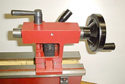
Well, no progress on the CNC but It was finally warm enough to go out and get some stuff done. I finally installed the cam lock for my lathe tail stock. I have had the box sitting here for a month but it was just too cold out in the garage. People that live up in the land of ice and snow will laugh at the temperature but when you live in what is basically the tropics, a freezing temperature just makes it miserable when you are accustomed to lows in range of 75F.
Not mine. Get yours here
It was a pain to get it turned the right way so it would lock on the ways. The alignment is different with the lock rings on so it was a matter of take it off, test, take it off, test. I finally got smart and punched a mark on the body so I could tell one side from the other. I still may need to shim it a bit with another washer. This was one of the most aggravating things about  my lathe. Having to stop and get in with a wrench to adjust the tail stock was a pain. There was really not much room so it meant turning 1/6 a revolution at a time to turn the nut.

I will go out in a bit to work on putting the other things on. I also picked up a lock for the saddle and a stop for they way. Those are quick and easy and just bolt into holes that are already tapped.  The main reason for all this is that I have also got a milling attachment for the lathe and I need to be able to lock down the saddle while milling.

This is really not related to the CNC project because I am forcing myself to use all off the shelf hardware for my CNC router. The whole process is like the chicken and the egg. It would be really easy to build myself a CNC machine using the machine shop I have access to at work. I could also just order one of the kits and bolt it together. The parts are readily available. CNC-Router Parts  and Fine Line Automation have some nice components that I could just buy and bolt together. I have actually bought some stuff from them for another project I am playing with. That is something different. With this project, I am just working on testing out my own ideas for building something different. A big part of it is that I don't want to use things that are not commonly available. The only things that I am using that are not regular hardware store fare are the electronics and the #25 chain. The same thing could be done with bicycle chain but I got such a cheap price on the chain that I cannot pass it up. I picked it up from Surplus Center. 60 cents a foot was quite an incentive.

There are some projects that are cool but totally unreasonable for people to reproduce. I look at projects that go like: Well, just take the leftover parts that are from 4 or 5 old CNC machines and then say, "Wow, I made a CNC machine!"

One the other end of the spectrum, you have projects like the Global Village Construction Set. The components they make are cool but completely unrealistic. Yes, if you have a fully equipped machine shop and welding equipment, you can make just about anything. What a surprise.

The OpenSourceMachine is a much more reasonable project. It is geared to making a machine shop from scrap that is really available. They are making a lathe, milling machine, and several other machines using things like engine blocks. This kind of bootstrap operation will do much more to help people make things starting from scratch.

Thursday, February 10, 2011

Brrrr. It's cold.

No, this is not an abandoned project. It is just too cold to work out in the garage and other stuff taking time.  Along with this project, I also have some work to do on my lathe and "those people" at work seem to want me to actually do some work.

More posts when there is something to say. Thanks for dropping by.

Sunday, February 6, 2011

Will it cut steel?

I see people keep asking if a CNC router would cut steel and aluminum. Why would you even want to?  It would be much simpler and cheaper to retrofit a metal cutting machine for CNC than trying to push a CNC router that hard. Even buying new, you could build a small CNC metal cutting mill for under $1200. A cheap SIEG X2 from Grizzly costs $500. You can pick up some steppers and a controller and you are in business. The only thing you would really need to make are the motor mounts and people sell those already made if you don't have the facilities. If you have the space and some patience, you can pick up a large mill off the used market for not really that much more money. Later, I might even make a CNC metal cutting mill. It would be fun to work with but it is not the same thing.

Tuesday, February 1, 2011

My Linear Bearing Plan

I have been thinking about this a long time. I don't like a lot of the linear bearing systems that are available. The nicest ones, are too expensive and generally too heavy for what I want for this machine. At the other end of the spectrum, the cheap and simple V-bearings, I really don't think are robust enough for long term use. I think that they make too small of a contact point, and will start eating up the rails with nicks over time. I wanted to design something that you could just go down to your local big box store and without many specialized woodworking or metalworking tools or skills, put together in an afternoon. I also wanted to leave the option for adjustment to keep them aligned and to be able to add bearing surface to make them stronger.   There have been bearings mounted on angle for a long time. It is simple and effective. It is just hard to mount them to anything to make a full bearing because they are odd shaped. My way around this problem is to use a readily available molding profile that they sell at lumber yards. They sell little filler strips that are triangular with 3/4 in sides. This is perfect for filling in the angle and giving a mounting surface.

You might need to knock off the apex of the angle to fit into the angle but this is quick and easy with a plane or sanding block.  This comes out a bit over 1 in wide at the base which can be sanded off, filled in or just ignored, depending on your aesthetics. You can then edge glue this to a rail that can be as wide as you would like to spread the load. If you would like, you can add additional bearings on the moving units to make a stronger support for higher loads. The stationary angle will only a bearing surface. You would not need to get very thick angle. It is being supported by the underlying wood and not structural. It could be glued on or anchored with screws either at the apex of the angle or along the edge. Just somewhere the bearings do not run. If you want a more long lasting surface or something stronger for working with harder materials, go with cold rolled steel.  You get the idea.

The movable bearing sections can be built up into units that you can mount the gantry or the Z axis depending on the location. The example here is a bit thin on the support but that is up to your final design choice. To make longer rails, all you need to do is butt the rail sections together, fill with expoxy (J-B Weld or such) and sand it even.  The rail can be almost fully supported except for the edge to give clearance for the bearings.

The last part would be how to support the overhanging bearing. That can be done with a small gusset that will support the extended arm or you can also make them into bolt on sub-units that can be adjustable for tracking and play. You can have multiple sliding units on each side of the gantry to broaden the stance of the gantry to make it more stable.

This is just a rough idea and the profiles will be developed more to fit in the different locations. Yes, I know there are other ways to make the profile to fit inside the angle. I am going under the assumption that people might not have a tablesaw, router table, shaper, chamfering bit for router, chamfering plane, drawknife,  or any of the other myriad ways that you could reproduce this profile. Again, people who may not have the woodworking skills or tools are the audience for this type of construction.