Thursday, June 2, 2011

Side tracked by my spindle.

Nothing to really show right now. I have been working on my spindle. I picked up an ER11 collet holder and set of collets that took a while to get here from Hong Kong. The holder I bought has an 8mm shaft. The plan is to use 608 bearings (skate bearings) for the spindle. As shipped, it would have been a press fit for the bearings but I want to be able to replace them easily. So, I chucked it up in the lathe and spend some quality time with some emery paper to bring the shaft down for a slip fit for the bearings. Well, it took quite a while with that hardened shaft.

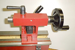
While I was doing that, I also finished adjusting my cam lock for my tailstock on my lathe.
Tailstock cam lock kit from LMS
I really like it but it was a pain to get set up. The installation was dead simple. Drill one hole in the web on the side of the tailstock and put it together. The pain was figuring out the orientation for the interior nut so that the threads line up where the quarter turn will pull the bolt tight. If you turn it one way, the thread is 1/2 turn off so it won't tighten quite enough to lock. Being a slow learner at times, the real solution was to use my center punch to mark one side of the nut so I could see when it was rotated 180 degrees. It would have been much simpler if I had done that from the beginning.

I did make a test run for the motor for the spindle. I have a 350 watt brushless motor:
Motor from Hobby King
  and a brushless motor contoller:
Brushless ESC from Hobby King
I started up the motor and ramped up the speed part way using an arduino. I am going to look later at controlling the spindle with my grblshield stepper shield but I have been waiting for the developer of grbl (a g-code interpreter for arduino) to get back to development so I can ask him a few questions regarding the spindle and limit switch controls. For now I am just running it with a different arduino.

The general idea for the spindle is like this:

But I am not really sure on the component placement yet. I think it will be shrouded with a place to hold the speed controller and also maybe a fan for cooling. I don't know how hot the motor will run under load and at speed.

Thursday, May 5, 2011

Things are moving along

Well, I have not been posting lately but I have been doing things.  I have my arduino based controller working and responding to g-code.  Just to fill you in, I have a grblshield and and arduino. The grblshield is a 3 axis stepper controller board for the arduino. So far, it is really nice to see motors actually moving.

I have decided that I will play with the smaller cnc machine for now. I will be using lead screws on this one. I have everything I really need for it.

I had considered using my little Proxxon X-Y table but I think I will reserve that for my little drill press.

Tuesday, April 26, 2011

Unhappy with bearings.

I have been playing with the bearing idea that I had. I am not really happy with them. I could make some adjusters for the bearings but I don't want them that complicated. I am going to have to give this some more thought. When I have a better plan, I will post.

Thursday, April 21, 2011

Test fitting the bearings and guide tube

My general overall impression is that this is going to be a good solution. By no means is this sample good enough to use but I was a bit anxious to see how things fit together. I just drilled the holes freehand because I really didn't know how things would fit together. There is a lot of stuff to potentially interfere. There are several clearance factors:
  • Clearing the fillet on the inside of the angle
  • The nut's clearance on the inside of the angle
  • The interference of the nuts and screw heads
 I was also concerned that the lengths of the screws were right. I had tested with some smaller screws for rough measurements but I knew that many things can go wrong once I started shimming things. The 25mm screws give me enough room for two shims and I could probably handle 4 flat washers and some lock washers on the 40mm screws. Right now, I didn't put any shims so it doesn't line up that well with the centerline of the tube but no point in messing with it until I have the spacing right. There is still lots of room for adjusting things.  I will be mounting the center bearing closer to the edge so I really won't need that many spacers on the short screws. I will probably need to counter-bore the the angle to seat the screw heads squarely. No big problem. It would be simpler to use the architectural angle that has a square inside corner but I will work with what I already have. 


I will now measure how far I need to space them to leave room for wrenches and make a fixture to hold the pieces for drilling on the drill press. It is also going to give a lot of space to mount other stuff to the complete carriages. I was also concerned that it would not be rigid enough but once I tighten up the screws, it stiffens up nicely. I could even make it more rigid by adding another bearing and screw in the middle but it would complicate getting things aligned. I could alternatively go with just some spacers.

Wednesday, April 13, 2011

Metric Rant

With the current world connection created by the Internet, I frequently hear people complain about the US measurement system. Let me let you in on the real problem with metric adoption: We really can't get metric stuff.

I ordered some screws for mounting my bearings. Regular skate bearings (608) have an 8mm bore. I can't just go up to the store and say, "I'm looking for some M8 screws. Let me have a box of 25mm and a box of 40mm." If they have any at all, they will be maybe one length and in little plastic bags of 4 screws for $3 or $4 as opposed to $0.06 for a SAE equivalent.

Instead, my only option is to order them online. Ok, first, I have to find a vendor that will sell less than 50 lb. boxes. Once I find some, I have to go ahead and order many more than I need or end up paying the same amount of money for less screws. I ordered a bag of 100 of the 25mm and another bag of 100 40mm. Well, I also needed washers and nuts. On top of that, I pay almost an additional 20% for shipping.

I had someone that was really surprised when I was talking about building my CNC mostly out of wood and gluing things together rather than all bolted together being a money saver. My fastener purchase was the single most expensive component of my CNC build. This includes things that I have had shipped half way around the world from Hong Kong to the US. The fasteners cost more than any other single component.

As long as we cannot just go down to a local store and things that are really metric, we will not convert to metric. We have this fake metric adoption where you get things in some funky measure like my coke can sitting next to me has a metric measure: 355ml.  It is the same 12 ounce size as it was before, they just put a conversion on it and say "*Poof*, it's metric." Same as when I work on my bike. Some things are really metric, some things are fake metric. We have things that are 25.4mm and 31.8mm which are the same size as when we were using non-metric measure 1", 1-1/4", 1-1/2" and such. So, not only do we have that, we also have them with other dimensions where the measurements that really are metric. So, we have a 1" bore on a 80mm shank so much that we just about have to carry around multiple measuring devices at all times. We also have to keep around two sets of tools because some parts are metric, some are not. I have duplicate wrenches, allen keys, measuring tapes, etc. One set in metric and one SAE. Even more fun is when the parts you are working on have a mix.

I can work with both systems and it doesn't really make any differences as they are all arbitrary. They both have advantages and disadvantages. I just wish we would have one or the other. Playing mix and match with both is just an absolute pain in the rear.
Sunday, April 10, 2011

Finalized Linear Bearing Plan


Ok, I have been thinking, and overthinking, the linear bearings. I have been unhappy with the ones that I have tested out before and finally have figured out what I want to do. I have not been happy with the idea of running hardened steel bearings on aluminum. I didn't want to mess with steel angle tracks because it is not as easy to work. I also wanted to keep the cost down. Here is the cheapest and easiest to work with plan that I have been able to develop.


This design uses 3/4" steel electrical conduit (EMT) for the rails.. It is straight and not expensive. It will also wear much better than the aluminum. A 10 foot piece was $4.33.  The 5 foot pieces I bought today are under $3 a piece at the borg. I could have gotten cheaper but I didn't want to mess with putting full 10 foot pieces in my car or driving around shopping.  If I were going with a more powerful router, I might consider using a thicker wall pipe or larger diameter tubing but I can't see it for a small router.

The bearings will be mounted on 3/4 in aluminum angle. This could be modified with larger angle to accommodate larger diameter tubing but I already have plenty of 3/4 in.  I ordered the screws today also. For the ones between the angles, I figure that 40mm will be plenty long and 25mm for the ones that stick out on top and bottom. I went with M8 screws. They are the right size for the 608 skate bearings without slop and will be stronger than smaller screws.  I also ordered lots of washers so I can shim the bearings to ride centered on the rails. I might put more bearings on each carriage mainly to make it more solid in case the angle starts flexing. I will see how it works once it is put together. I am also going to think about adding a shield around the bearings to keep it clean. Maybe some wipers on the ends.

The rails here are drawn to scale. The 3/4 in conduit is 0.931 in. OD. I plan on attaching it to the conduit with screws every 3 or 4 inches to tie the rails and support together. I might notch the support rail for the conduit to rest in but I will probably just add an epoxy fillet to secure and support the rail.  This rail assembly will have a wider backing plate behind it for adjustment.

If you would like the model for SketchUp, here is a link.

Wednesday, March 30, 2011

Manual machining stuff and rethinking bearing rails.

I have been doing a little manual machining to get ready to make some stuff for my CNC ideas.  I finally figured out how I can use my milling attachment on my little 7X10 lathe.

To make the milling attachment work, I added a milling table which is from an old Incra jig right angle fixture.


To mount it to the milling attachment, I just added a solid block of 1-1/4" x 1-1/4" aluminum to both clamp it into the attachment and also to provide a backing for the extrusion.


Next,  I will also make a vise and then a tooling plate for attaching other things like my rotary table.

In other news, I got a large bag of 8mm hex head cap screws for mounting 608 bearings. Of course I forgot to order some washers but that is life. I will pick a few up at the hardware store while I wait for an order of them to come from online.

I keep rethinking my bearing rail ideas and am considering going to a steel tubing rather than the aluminum angle for the bearings to run on. I just hate the idea of running the hardened steel bearings on something as soft as aluminum. It would be easy to make but I don't want to have to keep adjusting and replacing rails. I could go with a steel angle but it leaves me with the same problems and none of the advantages of using the aluminum rails.

I also got a shipping notification for my grblShield for my Arduino. If you are not familiar with it, it is a 3 axis controller board that attaches to an Arduino microcontroller. I have a parallel port breakout and stepper controller but I really want to try running it from the Arduino instead of the host computer. It is a trade off but I think it really is a better way to go. I can use my parallel breakout on a CNC lathe I have at work to play with and have all the electronics for another system using the arduino and 4 easy stepper drivers.  My ultimate goal is to get to the point of being able to do 4 and 5 axis routing but I am going to build the first machine to use to make further experiments.